A CNC model is a CNC prototype built before a product going into production, also known as a mock-up. According to different materials, it can be divided into CNC aluminum model and CNC plastic model. As the development of modern industry, more and more industries are paying attention to investment in R&D. In order to adapt to the quickly changing market, it is necessary to advance and accelerate the stage of product development using the CNC model. How to realize a CNC model? There’re some tips for assisting.
Preparation for a CNC model
1. Get ready for the 2D drawing and 3D model
For 2D and 3D files, the design can be done via many tools like Illustrator, Rhinoceros, AutoCAD, SolidWorks, Sketch-Up, etc.) All files should be scaled to the real size and units requiring
2. Determine the material
Different materials are applied in different industries, it’s important to select the right material for your CNC model. When selecting the material for a given application, there are several factors to consider. Some of the most critical include:
a. Mechanical function or appearance test
The purpose of the products influences the final material used. If some mechanical function is to be realized, the material may need to have better strength. If only for an appearance test, there’ll be more options.
b. Quantity
Quantity is one of the key factors determining the material. A different process is suitable for a different quantity, and different materials will be used during the different processes. Take aluminum, for example, ADC12 is used in die casting, while Al 6061 is used in CNC milling. If the quantity is 2000 pcs, using die casting will be much quicker and saving money, ADC12 will be an option in this situation.
c. Cost
d. Lead time
3. Determine the surface finish
In CNC modeling, various surface finishes are used. Surface finishing refers to the formation of a surface layer with special properties on the product surface of a material by chemical or physical means. Surface finishing improves the appearance, corrosion resistance, hardness, wear resistance, strength, and other properties of a part.
Some common finishes for CNC machined parts could be considered, such as as-machined, anodizing, powder coating, bead blasting, and painting, etc.
Choose a supplier for your CNC model
Concern and think about the below questions before making the decision.
(1) Qualification
A company with qualifications will be more cautious about quality control and customers’ satisfaction.
(2) The length of establishment
The longer the establishment time of the factory, the more experience it has.
(3) Technicians and Equipment
Technical equipment and professional staff are important components of a CNC factory and have an impressive impact on whether the CNC factory can run smoothly.
(4) Does the CNC factory’s expertise match your needs?
Having a supplier specialized in what you need is of many advantages. This will help increase your knowledge, accelerate your product development and make you more professional.
(5) After-sales service
How to treat complaints from customers is a key point in evaluating suppliers. Making mistakes is not terrible, what’s more, the matter is how to deal with the mistake.
Why choosing Wayken prototype for your CNC model
1. Quality:
WayKen is an ISO 9001 certified factory. Through the implementation of a total quality management system, we strengthen quality control and inspection in all processes of production, ensure optimization of the company’s processes and effective communication between customers and departments, as well as train employees in quality awareness and promote continuous technological upgrading to efficiently manufacture high-quality products.
2. Carbide Turning Inserts Experience and Technology:
Experience and technology play an important role in the field of CNC machining. Especially for some complex parts, Wayken will provide manufacturing design advice when evaluating, prior to manufacturing, the production department will review the parts again to make sure everything’s good and will help process trial assemble the parts for customers before shipment to make sure everything fits well.?
3. Service:
WayKen is not only good at providing quality products but also has a technical sales team taking good command of English and engineering communication. We provide quick response speed, in-time delivery, good packaging, and a positive attitude on complaints about your projects.
Summary
As an ISO 9001 certified factory, WayKen Rapid Deep Hole Drilling Inserts Manufacturing is a factory with advanced CNC machining equipment that provides CNC prototypes. Engineers and master craftsmen also have over 20 years of experience in this field. WayKen is able to provide the most timely and cost effective solutions and quotes. WayKen is committed to the satisfaction and success of every customer. If you have any questions, please contact us to experience our services.
The Carbide Inserts Website: https://www.estoolcarbide.com/
latheinserts
July 22, 2023
As machine tool spindles have gotten faster and more complex, the costs associated with repairing those spindles have increased. According to Tom Hoenig, president of GTI Spindle Technology, the average cost of spindle repair is now closer to $10,000 compared to $3,500 not so many years ago.
Mr. Hoenig’s company, a preventative maintenance and spindle repair specialist headquartered in Manchester, New Hampshire, commonly offers training seminars at machining facilities that address a variety of topics related to spindles. He says that 70 percent of spindle failures result from either a crash/impact between the spindle and the workpiece or fixture, or from spindle bearing contamination.
Crashes commonly occur because of human error, he explains. This includes programming mistakes, a misaligned tool, a toolholder improperly mated with the spindle, or fixturing that has been mounted incorrectly. And while crash sensors are now available on machine tools, they tend to mitigate damage rather than prevent Tungsten Carbide Inserts it from happening in the first place.
Spindle bearing contamination can occur when an operator directs an air hose at the spindle while blowing away coolant from the workpiece, fixtures other components. Mr. Hoenig says this can force particulate matter in the coolant into the spindle’s bearings. (Misdirected coolant nozzles can also cause this.) Positive-pressure “purging” seals are available to protect the interior of the spindle, but they can still be defeated by the high pressure of air or coolant streams.
In addition, the design of some high-speed spindles can make it difficult to prevent contamination. Traditional rotating components employ contact seals against contamination. In order to achieve the higher speeds that spindles require, the contact between rotating components needs to be Carbide Aluminum Inserts minimized, thus excluding contact seals from use and requiring what is known as “labyrinth seals,” which can permit contamination.
Beyond crashes and spindle bearing contamination, Mr. Hoenig says the remaining 30 percent of spindle failure is caused by lack of proper spindle lubrication, failure of spindle support equipment such as chillers, and failed connections within the machine tool’s electrical system.
So how can a shop go about protecting its increasingly hefty investment in machine tool spindles? Here are a few topics that GTI addresses in a typical spindle preventative maintenance seminar:
Preventing contamination of machining fluids.
Proper spindle installation and removal.
Bearing impact prevention.
Best tooling interface approaches.
Mr. Hoenig also suggests that shops consider investing in a portable vibration analysis unit that can be operated via a tablet app. The app works with an accelerometer, which is a piezoelectric measurement device used to measure specific vibration at particular frequencies. GTI’s accelerometers are now wireless and have a magnetic base for easy mounting to the spindle.
As for the frequency of testing, Mr. Hoenig recommends using it monthly, or particularly after a spindle crash/impact, in order to determine the exact spindle condition. Conducting this exercise on a monthly basis enables the user to watch the deterioration of the spindle over time. Conversely, outside service companies can be contracted to conduct periodic testing using one of these units. Some service providers, including GTI, also can attach a permanent-mount sensor to the spindle that uploads data to the cloud, where the company can monitor it and alert the shop when data show that a spindle problem may be imminent.
The Carbide Inserts Website: https://www.estoolcarbide.com/product/for-stainless-steel-lathe-turning-tools-cemented-carbide-turning-inserts-cnmg-series-pvd-coating/
latheinserts
July 20, 2023
Carbide inserts are virtually certain to have been used at some stage in the careers of all those who have done work with machines that cut metal. Inserts made of carbide for cutting tools are a product that cannot be overlooked in the metal cutting tool sector. Boring, turning, cutting, drilling, grooving, hobbing, milling, and threading are just some of the many applications that make use of them.
Carbide gives materials a high hot hardness in addition to a remarkable wear resistance when used in their construction. Carbide inserts are a superior option than high-speed steel when it comes to durability, making them a good pick for use in applications that require cutting metal. Coatings that provide additional resistance to wear, such as titanium nitride (TiN), titanium carbonitride (TiCN), titanium aluminum nitride (TiAlN), and aluminum titanium nitride (AlTiN), may lengthen the life of inserts by a significant amount. Examples of these coatings include titanium nitride (TiN), titanium carbonitride (TiCN), titanium aluminium nitride
Carbide inserts are manufactured in a large number of distinct geometric forms, each of which is customised specifically to each certain application in order for them to be able to carry out the various cutting processes. Carbide inserts are used in a variety of industries, including automotive, aerospace, and construction.
Carbide is more brittle than other standard tool materials, making it more subject to chipping and breaking, in addition to being more costly per unit than other typical tool materials. Because of these drawbacks, the carbide cutting tip itself is sometimes designed in the form of a tiny insert that is intended to be used in conjunction with a larger cutting tip on a tool whose shank is constructed from a different material, most frequently carbon tool steel. This provides the advantage of employing carbide at the cutting interface without the high expense and brittleness that would be associated with manufacturing the complete tool out of carbide. Carbide inserts are used in the majority of contemporary face mills, in addition to numerous lathe tools and end mills.
Inserts that are round or circular may be used for button milling, in addition to turning and splitting radius grooves. This is because of their versatility. Copy cutters, which are often referred to as button mills, are machines that make use of circular inserts that have a radiuses edge to a significant degree. Because of this, better feed rates and deeper cuts may be performed while consuming a much reduced amount of electricity. The transformation of radial grooves into a round component is referred to as “radius groove turning,” and the method is named after the term. Parting is the process of cutting through a section in its entirety, and the term refers to both the procedure and the result.
When one of the insert’s cutting edges is worn, it may be turned to a fresh, unused edge for shapes that are triangular, square, rectangular, diamond, rhombic, pentagon, and octagon. Other shapes that have multiple cutting edges include octagon, pentagon, and rhombic. Other forms, such as rhombuses, pentagons, and octagons, also contain many angles that may be used for cutting. These inserts have a variety of applications, including turning, boring, drilling, and grooving, to name a few of them. You may get more use out of an insert by utilizing its worn edges for roughing applications before rotating it to a fresh edge and using it for final machining. This will allow you to get more life out of the insert.
Carbide insert wear that is visible in woodcutting is caused, in great part, by chemical corrosion with the cobalt binder of the carbide (glue). Because of this, the tough tungsten particles are able to leach away, which results in a blunting of the cutting edge.
Carbide CNC inserts Process:
Batching
The absolute best raw material consists of a very fine spherical powder formed of cobalt, in addition to other compounds that have an extremely high level of purity. It is possible for each batch of powder to preserve its homogeneity and consistency throughout the production process by using the most cutting-edge mixing and wet milling technologies, in conjunction with accurate calculation.
Ball Milling
The nanotubes are reduced to an extremely fine powder by a process known as ball milling, which is a kind of grinding. This operation is also known as milling. During the process of ball milling, a localised high pressure will be formed as a consequence of the collision between the tiny hard balls that are enclosed in a concealed container. This collision will take place within the mill.
Spray Drying
Utilizing a spiral spray dryer tower allows for the powder to have an exceptional fluidity, which, in turn, leads to a density that is consistent throughout the carbide inserts blanks. This is the end product of the process. Our fixed tower, which is only committed to defined tasks, avoids any mixing of grains of varied sizes within a batch. This helps to ensure that the uniformity and high quality of each and every substrat is maintained throughout the production process.
Pressing
To get started, the material is put through a press that is highly automated, CNC controlled, and equipped with punches and dies so that it may be pressed into the necessary basic shape and size. The inserts, after being pressed, have a look that is quite similar to that of a true carbide insert; nevertheless, their hardness is not even close to meeting the requirements. Imported press machines and high-precision moulding machines, along with homogeneous spray powder, ensure that the density of the substrate body is comparable with the density of the clearance as well as the cutting edge of carbide inserts. This is accomplished by ensuring that the density of the substrate body is the same as that of the clearance. The grind value is delicately adjusted so that the whole surface and cutting edge are constant, as well as the tool’s durability and duration of use. This is done so that the tool may be used for a longer period of time.
Sintering
In order to get the desired result of increased brittleness, the insert is subjected to a heat treatment that lasts for 15 hours and is carried out at a temperature of 1500 degrees Celsius. Sintering is the process by which the molten cobalt and tungsten carbide particles are brought together and bonded together. First, the insert goes through a significant shrinkage, and this shrinkage must be precise in order to achieve the appropriate tolerance; second, the powder mixture is transformed into a new metallic material that is known as cemented carbide. The treatment process that takes place in the sintering furnace accomplishes two goals. The cobalt magnetic pole tolerance on the inside of the sintering furnace is guaranteed carbide drilling inserts to be within 0.3, and the magnetic force is guaranteed to be within 0.5. Neither of these parameters may be outside of their respective ranges. Carbide inserts that are manufactured using a large number of batches have remarkable stability. This is because even the smallest amount of variation is sufficient to minimise the quality variation of each batch to a minimum as much as is humanly feasible.
The following phase in the process, which comes after the insert has achieved the necessary amount of hardness, is to bring it to a point where it can be delivered to the customer. Before going on to the next step of manufacture, we will first use the coordinate measuring equipment to do a comprehensive check to confirm that the size of the insert satisfies all of the parameters. This will be done before we move on to the next stage.
Gross Inspection
When doing quality control on the raw materials, it is necessary to make use of a carbon-sulfur analyzer. This is done to ensure that the tungsten carbide powder has an adequate amount of both carbon and Sulphur.
After the sintering process, the material is examined using a variety of tools, including the following: Conduct tests to determine the TRS of the carbide rod, as well as its microstructure, cobalt concentration, and the material’s hardness. Include a dropping test to confirm that there is no flaw in the material in the centre or inside of the blank. Additionally, include an ultrasonic scanner for carbide die blanks to check that there is no sand hole inside the blank.
After being sintered, the material is subjected to a manual examination, which it must pass. Carburization and decarburization, sand holes in the surface, and tiny fissures are some of the things that should be looked for while doing a visual inspection of the material to determine whether or not it is flawed.
After sintering, the sizes are checked using the following criteria: A micrometer will be used to measure the dimensions, and an additional test for roundness will be performed on carbide rods.
Grinding
Diamonds are used in the grinding process so that the carbide insert will ultimately have the correct shape after the operation is finished. In order for the inserts to be of a quality that is commensurate with the requirements imposed by the geometric angles, they are ground using a variety of techniques. Throughout the process of grinding, the insert is subjected to checks and measurements by the grinder’s built-in measuring control at a number of different places.
Semi-Inspection
After yet another visit to the lab for a quality check, the top and bottom of the insert are ground to the right thickness. This completes the manufacturing process. The stage that we are now at is called the semi-inspection. Grinding cemented carbide, which is the hardest material that humans have ever discovered, needs industrial diamond, which is the hardest mineral that exists on any planet.
Passivation
After the insert has had its thickness reduced to the proper level, it is subjected to further grinding in order to create the ideal form and dimensions for it. Higher standards, both in terms of performance and stability, have been imposed on cutting tools in order to meet the needs of contemporary high-speed cutting and automated machine tools. In particular, coated tools have to go through the process of passivation before they can be coated. This is done to guarantee that the coating will be durable and will last for a long time. The objective of the edge passivation technology is to solve the issue of the micro notch defect that is left on the edge of the carbide inserts after grinding, to reduce or eliminate the edge value, and to achieve the objective of making the edge smooth, sharp, and durable.
Cleaning
Once the inserts have been machined, the next step is for them to be cleaned, and then they are shipped to be coated. When working with the inserts at this stage, it is imperative that protective gloves be used so that no oil or dust gets on the hands. They are given a coating after first being positioned into fixtures that are fastened to a carousel and then being placed within an oven that maintains a low pressure. This is the component of the insert that is responsible for giving it its unique color.
Coating
Not only does it completely relieve the internal tension of the substrate, but it also removes the unevenly high edges of the carbide inserts, which means that the continuity and consistency of the edge of each carbide insert is substantially improved. The state-of-the-art sandblasting and grinding equipment that are equipped with the pre-coating treatment method that was created by our company make this accomplishment feasible.
Chemical vapour deposition, often known as CVD, and physical vapour deposition are the names of the two methods that are used to coat objects in today’s world (PVD). The nature of the material and the processing procedure come into play when deciding which coating method to use. The thickness of the coating is going to be determined by the application of the insert, and the thickness of the coating is going to have an effect on the durability and the life of the insert. The surface of the cemented carbide is coated with a number of very thin coatings, including as titanium carbide, aluminum oxide, and titanium nitride. These coatings have the potential to considerably prolong the material’s service life and durability. The fact that there are a lot of coatings is the closely guarded technical secret behind this.
Before adding gaseous chloride and oxide, as well as methane and hydrogen, the insert has to be positioned within the furnace in the event that the coating procedure involves the CVD approach. These gases interact with one another and also take action on the surface of the cemented carbide to generate the insert when the temperature reaches one thousand degrees Celsius. You will wind up with an even coating that is no thicker than a few thousandths of a millimeter at most. This will be the result of your efforts. The value of some coated inserts goes up because the surface is given a golden finish. In addition, the lifespan of the coated inserts is much longer than that of the untreated inserts by a factor of five. PVD is sprayed onto the insert while it is heated at a temperature of 400 degrees Celsius.
Inspection
Following the completion of the final inspection, each insert is checked against the blueprints and the batch order to ensure that it meets the standards. After that, you may finally start packing it. After having the proper grade laser-etched into the insert, it is then placed in a grey box that has a printed label affixed to it. Finally, the insert is given its final presentation. It is now ready to be distributed to the many customers who purchased it. On the insert box, you’ll find not only information about the product, but also the date, as well as the serial number.
Why Carbide Inserts Are So Great?
- When compared to other types of tools, carbide inserts provide superior levels of productivity and cost effectiveness.
- Carbide is a particularly durable substance, which results in a significantly increased amount of time-spent working.
- Tungsten carbide is available in more than a dozen distinct grades, and each of these grades has the potential to be used for a variety of purposes.
- Carbide materials, when used as cutting tools, give a surface finish quality that is much superior to that of other materials.
In addition, carbide recycling materials such as carbide inserts may be used to a wide variety of purposes, which makes these materials an important component for a lot of different companies. Let’s take a more in-depth look, shall we?
Tungsten carbide is one of the most often used instruments because it is both precise and long-lasting, two qualities that are essential for a variety of medical operations. One of the most noteworthy applications for carbide is in surgical instruments. Tungsten carbide is used to manufacture the tip of the blade of the tool as well as the end of the utensil, despite the fact that the base of the tool itself is normally fashioned from titanium or stainless steel.
Carbide is an excellent material for jewelers all over the world to use, not just for the shape of jewelry but also for the jeweler itself. Tungsten is an excellent material for wedding rings and other types of jeweler because of its high level of hardness, which places it just slightly below that of diamonds. In addition, jewelers have to depend on effective tools in order to work on these items, and carbide is an excellent material for that purpose. What’s not to like about tungsten jeweler, since it has a great appearance, is highly durable, and is often less expensive than gold?
Carbide has also shown to be an efficient neutron reflector in several applications. This robust substance was also employed during the early research into nuclear chain reactions, notably for the protection of weapons during those early studies. Although the usage of carbide in this business is not quite as prevalent as it may be in some of the others, it is very essential that anybody working with any kind of material do so in the most careful manner possible..
Conclusion
The insert grade that you employ may make all the difference in the world when it comes to how productive your manufacturing process is, and this is true regardless of the size, material, or design of the component. You may keep ahead of the competition by choosing the appropriate insert for the particular machining process you will be doing. Inserts are an essential part of the metal cutting process and cannot be imagined without them. The inserts themselves are crafted from some of the most abrasive substances that can be found anywhere in the globe.
Carbide inserts manufacturers like HUANA are able to fulfil the demands for ever-increasing feeds and speeds, as well as the need for longer tool life and reduced costs, by continuously refining the designs of tungsten carbide inserts and creating better and better coating methods. As one of the leading manufacturers of carbide inserts, HUANA offers the best cutting tool solution for almost any application or machining process. With a variety of inserts and insert configurations that have been designed specifically for different metals, such as steels, stainless steel, cast iron, and aluminum alloy, HUANA is able to cater to a wide range of cutting needs. Whether you are roughing, grooving, finishing, or doing any of the various forms of machining. Due to the extensive variety of carbide insert goods and solutions that we provide, we are certain that you will find exactly what you are looking for.
The Carbide Inserts Website: https://www.estoolcarbide.com/cutting-tool-inserts/wnmg-insert/
latheinserts
July 17, 2023
Carbide inserts are virtually certain to have been used at some stage in the careers of all those who have done work with machines that cut metal. Inserts made of carbide for cutting tools are a product that cannot be overlooked in the metal cutting tool sector. Boring, turning, cutting, drilling, grooving, hobbing, milling, and threading are just some of the many applications that make use of them.
Carbide gives materials a high hot hardness in addition to a remarkable wear resistance when used in their construction. Carbide inserts are a superior option than high-speed steel when it comes to durability, making them a good pick for use in applications that require cutting metal. Coatings that provide additional resistance to wear, such as titanium nitride (TiN), titanium carbonitride (TiCN), titanium aluminum nitride (TiAlN), and aluminum titanium nitride (AlTiN), may lengthen the life of inserts by a significant amount. Examples of these coatings include titanium nitride (TiN), titanium carbonitride (TiCN), titanium aluminium nitride
Carbide inserts are manufactured in a large number of distinct geometric forms, each of which is customised specifically to each certain application in order for them to be able to carry out the various cutting processes. Carbide inserts are used in a variety of industries, including automotive, aerospace, and construction.
Carbide is more brittle than other standard tool materials, making it more subject to chipping and breaking, in addition to being more costly per unit than other typical tool materials. Because of these drawbacks, the carbide cutting tip itself is sometimes designed in the form of a tiny insert that is intended to be used in conjunction with a larger cutting tip on a tool whose shank is constructed from a different material, most frequently carbon tool steel. This provides the advantage of employing carbide at the cutting interface without the high expense and brittleness that would be associated with manufacturing the complete tool out of carbide. Carbide inserts are used in the majority of contemporary face mills, in addition to numerous lathe tools and end mills.
Inserts that are round or circular may be used for button milling, in addition to turning and splitting radius grooves. This is because of their versatility. Copy cutters, which are often referred to as button mills, are machines that make use of circular inserts that have a radiuses edge to a significant degree. Because of this, better feed rates and deeper cuts may be performed while consuming a much reduced amount of electricity. The transformation of radial grooves into a round component is referred to as “radius groove turning,” and the method is named after the term. Parting is the process of cutting through a section in its entirety, and the term refers to both the procedure and the result.
When one of the insert’s cutting edges is worn, it may be turned to a fresh, unused edge for shapes that are triangular, square, rectangular, diamond, rhombic, pentagon, and octagon. Other shapes that have multiple cutting edges include octagon, pentagon, and rhombic. Other forms, such as rhombuses, pentagons, and octagons, also contain many angles that may be used for cutting. These inserts have a variety of applications, including turning, boring, drilling, and grooving, to name a few of them. You may get more use out of an insert by utilizing its worn edges for roughing applications before rotating it to a fresh edge and using it for final machining. This will allow you to get more life out of the insert.
Carbide insert wear that is visible in woodcutting is caused, in great part, by chemical corrosion with the cobalt binder of the carbide (glue). Because of this, the tough tungsten particles are able to leach away, which results in a blunting of the cutting edge.
Carbide CNC inserts Process:
Batching
The absolute best raw material consists of a very fine spherical powder formed of cobalt, in addition to other compounds that have an extremely high level of purity. It is possible for each batch of powder to preserve its homogeneity and consistency throughout the production process by using the most cutting-edge mixing and wet milling technologies, in conjunction with accurate calculation.
Ball Milling
The nanotubes are reduced to an extremely fine powder by a process known as ball milling, which is a kind of grinding. This operation is also known as milling. During the process of ball milling, a localised high pressure will be formed as a consequence of the collision between the tiny hard balls that are enclosed in a concealed container. This collision will take place within the mill.
Spray Drying
Utilizing a spiral spray dryer tower allows for the powder to have an exceptional fluidity, which, in turn, leads to a density that is consistent throughout the carbide inserts blanks. This is the end product of the process. Our fixed tower, which is only committed to defined tasks, avoids any mixing of grains of varied sizes within a batch. This helps to ensure that the uniformity and high quality of each and every substrat is maintained throughout the production process.
Pressing
To get started, the material is put through a press that is highly automated, CNC controlled, and equipped with punches and dies so that it may be pressed into the necessary basic shape and size. The inserts, after being pressed, have a look that is quite similar to that of a true carbide insert; nevertheless, their hardness is not even close to meeting the requirements. Imported press machines and high-precision moulding machines, along with homogeneous spray powder, ensure that the density of the substrate body is comparable with the density of the clearance as well as the cutting edge of carbide inserts. This is accomplished by ensuring that the density of the substrate body is the same as that of the clearance. The grind value is delicately adjusted so that the whole surface and cutting edge are constant, as well as the tool’s durability and duration of use. This is done so that the tool may be used for a longer period of time.
Sintering
In order to get the desired result of increased brittleness, the insert is subjected to a heat treatment that lasts for 15 hours and is carried out at a temperature of 1500 degrees Celsius. Sintering is the process by which the molten cobalt and tungsten carbide particles are brought together and bonded together. First, the insert goes through a significant shrinkage, and this shrinkage must be precise in order to achieve the appropriate tolerance; second, the powder mixture is transformed into a new metallic material that is known as cemented carbide. The treatment process that takes place in the sintering furnace accomplishes two goals. The cobalt magnetic pole tolerance on the inside of the sintering furnace is guaranteed carbide drilling inserts to be within 0.3, and the magnetic force is guaranteed to be within 0.5. Neither of these parameters may be outside of their respective ranges. Carbide inserts that are manufactured using a large number of batches have remarkable stability. This is because even the smallest amount of variation is sufficient to minimise the quality variation of each batch to a minimum as much as is humanly feasible.
The following phase in the process, which comes after the insert has achieved the necessary amount of hardness, is to bring it to a point where it can be delivered to the customer. Before going on to the next step of manufacture, we will first use the coordinate measuring equipment to do a comprehensive check to confirm that the size of the insert satisfies all of the parameters. This will be done before we move on to the next stage.
Gross Inspection
When doing quality control on the raw materials, it is necessary to make use of a carbon-sulfur analyzer. This is done to ensure that the tungsten carbide powder has an adequate amount of both carbon and Sulphur.
After the sintering process, the material is examined using a variety of tools, including the following: Conduct tests to determine the TRS of the carbide rod, as well as its microstructure, cobalt concentration, and the material’s hardness. Include a dropping test to confirm that there is no flaw in the material in the centre or inside of the blank. Additionally, include an ultrasonic scanner for carbide die blanks to check that there is no sand hole inside the blank.
After being sintered, the material is subjected to a manual examination, which it must pass. Carburization and decarburization, sand holes in the surface, and tiny fissures are some of the things that should be looked for while doing a visual inspection of the material to determine whether or not it is flawed.
After sintering, the sizes are checked using the following criteria: A micrometer will be used to measure the dimensions, and an additional test for roundness will be performed on carbide rods.
Grinding
Diamonds are used in the grinding process so that the carbide insert will ultimately have the correct shape after the operation is finished. In order for the inserts to be of a quality that is commensurate with the requirements imposed by the geometric angles, they are ground using a variety of techniques. Throughout the process of grinding, the insert is subjected to checks and measurements by the grinder’s built-in measuring control at a number of different places.
Semi-Inspection
After yet another visit to the lab for a quality check, the top and bottom of the insert are ground to the right thickness. This completes the manufacturing process. The stage that we are now at is called the semi-inspection. Grinding cemented carbide, which is the hardest material that humans have ever discovered, needs industrial diamond, which is the hardest mineral that exists on any planet.
Passivation
After the insert has had its thickness reduced to the proper level, it is subjected to further grinding in order to create the ideal form and dimensions for it. Higher standards, both in terms of performance and stability, have been imposed on cutting tools in order to meet the needs of contemporary high-speed cutting and automated machine tools. In particular, coated tools have to go through the process of passivation before they can be coated. This is done to guarantee that the coating will be durable and will last for a long time. The objective of the edge passivation technology is to solve the issue of the micro notch defect that is left on the edge of the carbide inserts after grinding, to reduce or eliminate the edge value, and to achieve the objective of making the edge smooth, sharp, and durable.
Cleaning
Once the inserts have been machined, the next step is for them to be cleaned, and then they are shipped to be coated. When working with the inserts at this stage, it is imperative that protective gloves be used so that no oil or dust gets on the hands. They are given a coating after first being positioned into fixtures that are fastened to a carousel and then being placed within an oven that maintains a low pressure. This is the component of the insert that is responsible for giving it its unique color.
Coating
Not only does it completely relieve the internal tension of the substrate, but it also removes the unevenly high edges of the carbide inserts, which means that the continuity and consistency of the edge of each carbide insert is substantially improved. The state-of-the-art sandblasting and grinding equipment that are equipped with the pre-coating treatment method that was created by our company make this accomplishment feasible.
Chemical vapour deposition, often known as CVD, and physical vapour deposition are the names of the two methods that are used to coat objects in today’s world (PVD). The nature of the material and the processing procedure come into play when deciding which coating method to use. The thickness of the coating is going to be determined by the application of the insert, and the thickness of the coating is going to have an effect on the durability and the life of the insert. The surface of the cemented carbide is coated with a number of very thin coatings, including as titanium carbide, aluminum oxide, and titanium nitride. These coatings have the potential to considerably prolong the material’s service life and durability. The fact that there are a lot of coatings is the closely guarded technical secret behind this.
Before adding gaseous chloride and oxide, as well as methane and hydrogen, the insert has to be positioned within the furnace in the event that the coating procedure involves the CVD approach. These gases interact with one another and also take action on the surface of the cemented carbide to generate the insert when the temperature reaches one thousand degrees Celsius. You will wind up with an even coating that is no thicker than a few thousandths of a millimeter at most. This will be the result of your efforts. The value of some coated inserts goes up because the surface is given a golden finish. In addition, the lifespan of the coated inserts is much longer than that of the untreated inserts by a factor of five. PVD is sprayed onto the insert while it is heated at a temperature of 400 degrees Celsius.
Inspection
Following the completion of the final inspection, each insert is checked against the blueprints and the batch order to ensure that it meets the standards. After that, you may finally start packing it. After having the proper grade laser-etched into the insert, it is then placed in a grey box that has a printed label affixed to it. Finally, the insert is given its final presentation. It is now ready to be distributed to the many customers who purchased it. On the insert box, you’ll find not only information about the product, but also the date, as well as the serial number.
Why Carbide Inserts Are So Great?
- When compared to other types of tools, carbide inserts provide superior levels of productivity and cost effectiveness.
- Carbide is a particularly durable substance, which results in a significantly increased amount of time-spent working.
- Tungsten carbide is available in more than a dozen distinct grades, and each of these grades has the potential to be used for a variety of purposes.
- Carbide materials, when used as cutting tools, give a surface finish quality that is much superior to that of other materials.
In addition, carbide recycling materials such as carbide inserts may be used to a wide variety of purposes, which makes these materials an important component for a lot of different companies. Let’s take a more in-depth look, shall we?
Tungsten carbide is one of the most often used instruments because it is both precise and long-lasting, two qualities that are essential for a variety of medical operations. One of the most noteworthy applications for carbide is in surgical instruments. Tungsten carbide is used to manufacture the tip of the blade of the tool as well as the end of the utensil, despite the fact that the base of the tool itself is normally fashioned from titanium or stainless steel.
Carbide is an excellent material for jewelers all over the world to use, not just for the shape of jewelry but also for the jeweler itself. Tungsten is an excellent material for wedding rings and other types of jeweler because of its high level of hardness, which places it just slightly below that of diamonds. In addition, jewelers have to depend on effective tools in order to work on these items, and carbide is an excellent material for that purpose. What’s not to like about tungsten jeweler, since it has a great appearance, is highly durable, and is often less expensive than gold?
Carbide has also shown to be an efficient neutron reflector in several applications. This robust substance was also employed during the early research into nuclear chain reactions, notably for the protection of weapons during those early studies. Although the usage of carbide in this business is not quite as prevalent as it may be in some of the others, it is very essential that anybody working with any kind of material do so in the most careful manner possible..
Conclusion
The insert grade that you employ may make all the difference in the world when it comes to how productive your manufacturing process is, and this is true regardless of the size, material, or design of the component. You may keep ahead of the competition by choosing the appropriate insert for the particular machining process you will be doing. Inserts are an essential part of the metal cutting process and cannot be imagined without them. The inserts themselves are crafted from some of the most abrasive substances that can be found anywhere in the globe.
Carbide inserts manufacturers like HUANA are able to fulfil the demands for ever-increasing feeds and speeds, as well as the need for longer tool life and reduced costs, by continuously refining the designs of tungsten carbide inserts and creating better and better coating methods. As one of the leading manufacturers of carbide inserts, HUANA offers the best cutting tool solution for almost any application or machining process. With a variety of inserts and insert configurations that have been designed specifically for different metals, such as steels, stainless steel, cast iron, and aluminum alloy, HUANA is able to cater to a wide range of cutting needs. Whether you are roughing, grooving, finishing, or doing any of the various forms of machining. Due to the extensive variety of carbide insert goods and solutions that we provide, we are certain that you will find exactly what you are looking for.
The Carbide Inserts Website: https://www.estoolcarbide.com/product/tcmt-steel-inserts-cnc-lathe-turning-p-1204/
latheinserts
July 14, 2023
latheinserts
July 12, 2023
Milling with high levels of automation is a flexible machining method that can produce components in virtually any shape. In the manufacturing industry, there is a wide range of applications for the many distinct types of CNC milling processes. The primary distinction between end milling and other techniques is the kind of tooling that is utilized during the cutting of the material. This page will provide an overview of the many kinds of end mills, as well as the process of end milling and the various fields of industry in which end mills are used.
What Precisely Is End Milling?
Milling is a procedure that may be used to create a variety of milling components, including slots, shoulders, die holes, curves, and profiles. One sort of milling is called end milling. When performing end milling, a cylindrical cutter known as an end mill is utilized. This cutter features several cutting edges on both its perimeter and its tip, allowing it to do both end cutting and peripheral cutting.
What Exactly Does “End Mill” Mean?
The end mill is a type of milling cutter that is capable of cutting in an axial direction. It may be used for end milling, profile milling, tracer milling, face milling, and plunging, among other applications. End mills and other types of cutting tools can be fabricated from a variety of materials, including carbide inserts (which are designed for high production milling), high-speed steel (which is used when a specific tool shape is required), ceramics inserts (which are designed for high-speed machining with high volume), and diamond inserts (offer tight tolerances). When it comes to the construction of end mills, high-speed steel (HSS) and tungsten carbide are two of the most often used materials. The use of end mills enables precise cutting, which may then be used to make milled components for a variety of purposes, such as manufacturing jewelry, signs, moulds, circuit boards, wood engravings, and machine parts, among other things. End mills can be purchased in a wide variety of lengths, sizes, kinds, and flute configurations.
Various Models of End Mills
The square end mill, also known as the flat end mill, is a general-purpose mill that generates flat-surfaced cuts with exact 90° corners in the workpiece. This incorporates milling operations such as side milling, face milling, and more. The roughing step as well as the finishing stage are both appropriate uses for square end mills. These mills have pointed corners that provide an angle of 90 degrees at each intersection. They can have a single end or a double end, and they can be formed of solid carbide or various compositions of high-speed steel. Additionally, they can have a single end or a double end. Carbide square end mills produce the highest volume of work. They might have a broad purpose or they can have a high performance geometry. It is possible to plunge, groove, side mill, face mill, and counter bore with them. These milling cutters are the most often used in the manufacturing sector. They come in a size range that spans a broad spectrum of diameters.
A ball nose end mill with a radius at the bottom generates a rounded pass and is suitable for 3D contour work, shallow slotting, pocketing, and contouring applications because it provides a higher surface polish and makes for a superior overall quality. The edges of this tool are ground to be centre cutting, and the end of the tool has a complete radius that is equal to half the diameter of the tool. They can have a single end or a double end, and they can be formed of solid carbide or various compositions of high speed steel. Additionally, they can have a single end or a double end. They might have a broad purpose or they can have a high performance geometry. Milling a full radius groove, milling contours or profiles, and milling corners with a wide radius are all possible uses for these tools. For engraving purposes, the lower diameters can be employed. They may be purchased in a broad range of conventional lengths and sizes to suit your needs.
Radius end mills have a square nose with slightly rounded corners that assist disperse cutting forces uniformly. This helps avoid damage to the end mill and extends its life. In milling applications that need a certain radius, these end mills are turned against a workpiece to form a flat-bottomed groove with slightly rounded inner corners. They are also often referred to as bull-nose end mills. In order to prevent damage to either the end mill or the workpiece, the cutting head of each end mill is equipped with flutes that convey chips away from the workpiece. On milling machines, whether CNC or manual, radius end mills are utilized.
Roughing end mills, which are often referred to as hog mills, are utilized in situations when huge volumes of material need to be removed in a hurry. The shape of the teeth permits very little to no vibration, although the finish is more jagged as a result. Roughing End Mills, which are also known as ripping cutters or hoggers, are designed to remove huge quantities of metal more rapidly and effectively than normal end mills. Roughing end mills can also be referred to as hoggers. Before beginning the finishing process, roughing end mills are used to remove big chips from low-to-medium carbon steel and alloy steel in order to make heavy cuts, deep slotting, and quick stock removal. Roughing end mills with fine teeth remove less material than standard end mills, but the pressure is dispersed over many more teeth, which results in longer tool life and a smoother finish on high temperature alloys and stainless steel.
Micro end mills are those that have a diameter that is less than 100 micrometres. When the accessibility for machining is governed by the tool diameter, they are frequently utilized for cutting ductile materials for constructions that have short radii, undercuts, and tool diameter determined geometries. Micro end mills with high-speed cutting for use in micromachining; these mills are of a quality that is unique in the world of microtools; they can be used for metalworking with steel, graphite, stainless steel, copper, titanium, cast iron, grey cast iron, non-ferrous metals, aluminum, gold, as well as composites and plastics.
In long reach and deep pocketing applications, long neck end mills offer the most strength. The Long Neck End Mill Series provides low burrs while enabling very accurate copper electrode cutting. High grade copper electrode machining was created by sharpness shearing capability and DLC coating. Developed long-lasting machining on the Copper metal.
Applications of End Mills in Different Industries
Mold processing
Die and mold manufacturing is a specialist field that needs both common and specialized equipment, notably milling cutters, to allow the manufacture of small batches for particular uses. As opposed to conventional mould steels like P-20 and H1355-60HRC Carbide End Mill, clients are increasingly specifying metal for work at mold shops. Aluminum alloys have various benefits for molding, including great machinability, high strength-to-weight ratio, and superior thermal conductivity. Metal removal rates from carbide end mills with the proper cutting geometry and coatings can be four to five times greater than those from moulded steel. Mold finishing time is greatly decreased by readily achieving surface finishes of 16 or higher.
Heat-Resistant Alloy Machining
Traditionally, the highest grade tungsten carbide has been used to create end mills. They have sharp teeth as a result of their design, which enables them to polish with extreme accuracy while yet retaining a high level of brightness. The end mills may be counted on to carry out their intended function even under challenging circumstances. One of the numerous uses for this tool, which also serves a variety of other objectives, is the machining of heat-resistant alloys like titanium, stainless steel, and other materials. Some end mills can be used in processes that are carried out at high temperatures because they have a surface that is much more abrasive. Some end mills have a substantially greater range of sizes and shapes than typical end mills and a significantly higher level of abrasiveness.
3C Processing
Aluminum and plastics are the two materials most frequently utilized in the 3C sector. Glass, ceramics, and stainless steel have now been included. End mill providers have significant demands as a result of the intense competitiveness in the 3C industry, which necessitates both quick delivery and exceptionally long tool lives. The 3C electronic, parts machining, and precision mould machining industries mostly employ cemented carbide inserts the long neck and micro end mills. The mobile phone, digital, and other electronic goods in the 3C sector are specifically designed for the micro end mill and long neck end mills. They realize the most professional and highest quality processing requirements and have superior production accuracy. These end mills are more durable and produce products with extremely high finishes. comprehensive tool selection in one location.
Aviation Industry
In the aviation sector, milling is widespread. For the components of aircraft wings and engines, complex end mills are employed. In the aviation sector, end mills are now one of the most crucial machining techniques, particularly when working with aluminum alloys.
Aerospace components not only make extensive use of innovative structures, technologies, and materials, but also their intricate design and lack of stiffness need the extensive use of high performance standard end mills and specialized carbide end mills to process components like engines. The carbide end mill system can readily interfere with components and holders while cutting elevated portions. As a result, it’s essential to optimize the route of the carbide milling tool, employing techniques like spiral interpolation for milling and inserting and milling rather than side milling or straight milling. A powerful machining center must be used to manufacture the turbine cartridge in terms of tooling. The analysis of the processing procedure shows that the chassis requires roughing, semi-finishing, and finishing. In the production of such aerospace components, high performance carbide end mills can be used for roughing, standard high performance carbide end mills, and non-standard high performance unique carbide end mills for semi-finishing and finishing.
Metal Manufacturing
Carbide end mills come in a broad range of lengths, diameters, flute counts, and other characteristics. They are selected based on the material they are cutting and the level of surface quality needed for the job. A highly sharp cutting edge and a tiny radius are only two of the properties that make carbide end mills excellent for use in metalworking operations including turning, milling, drilling, and tapping. For many metal production applications, carbide end mills provide a reliable and long-lasting option. In comparison to other end mill materials, it has various benefits including a long usable life, the capacity to cut at extremely high speeds, and a superior final surface.
A type of industrial equipment called a carbide end mill is used to cut and shape metals and other solid materials. Cast iron, non-ferrous metals, alloys, and polymers are among of the toughest materials, and carbide end mills are employed for high-speed operations on these materials because of their exceptional heat resistance. A345 solid carbide end mills are used to machine non-ferrous metals like aluminum, brass, and copper, whereas 45–50 HRC carbide end mills are required to machine steel. Additionally, the mould P20 steel requires 55–60 HRC Carbide End Mills.
Conclusion
Multiple-flute cutters made of carbide are commonly used for cutting plastics or metals. They generally feature two or more helical flutes and are placed vertically. Typically, end mills are set up to cut on both sides and with their ends. The required finish type must be taken into account when choosing an end mill. Understanding the machine’s cutting capacity requires knowledge about the end mill’s material. Steel is utilized for conventional metal machining, although hard materials like carbide, cobalt, and diamond can be employed in high-speed applications. In milling operations including profile milling, tracer milling, face milling, plunging, contouring, slotting, drilling, and reaming, carbide end mills are employed. There are several major groups of carbide end mill tools.
The Carbide Inserts Website: https://www.estoolcarbide.com/product/rcgt-aluminum-insert-for-cnc-indexable-tools-p-1217/
latheinserts
July 11, 2023
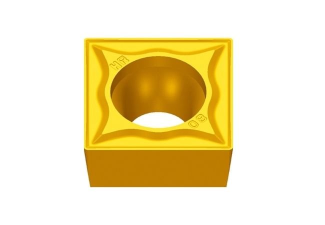
ESTool SCMT Insert
Description:
ESTool SCMT Insert, 90° Square Indexable Carbide Turning Insert.?7° positive flank inserts for semi-finishing and finish turning. Chip breaking in moderate feed range. Positive rake, low cutting forces. Our general-purpose grade is designed to cut most materials including?stainless steels, mild steel, brass, bronze, aluminium and cast iron.
Feature:
- 90° Square insert
- Single sided
- Positive rake
- 7° side clearance
- Low cutting forces
| ESTool SCMT Insert |
| HF |
| Insert shape |
?Type |
?Size (mm) |
| L |
ΦI.C |
S |
Φd |
r |
| HF? Finishing |
SCMT09T302-HF |
9.525 |
9.525 |
3.97 |
4.4 |
0.2 |
| SCMT09T304-HF |
9.525 |
9.525 |
3.97 |
4.4 |
0.4 |
| SCMT09T308-HF |
9.525 |
9.525 |
3.97 |
4.4 |
0.8 |
| EF |
| Insert shape |
?Type |
?Size (mm) |
| L |
ΦI.C |
S |
Φd |
r |
| EF Finishing |
SCMT09T302-EF |
9.525 |
9.525 |
3.97 |
4.4 |
0.2 |
| SCMT09T304-EF |
9.525 |
9.525 |
3.97 |
4.4 |
0.4 |
| SCMT09T308-EF |
9.525 |
9.525 |
3.97 |
4.4 |
0.8 |
| HM |
| Insert shape |
?Type |
?Size (mm) |
| L |
ΦI.C |
S |
Φd |
r |
| HM? Semi-finishing |
SCMT09T304-HM |
9.525 |
9.525 |
3.97 |
4.4 |
0.4 |
| SCMT09T308-HM |
9.525 |
9.525 |
3.97 |
4.4 |
0.8 |
| SCMT120404-HM |
12.7 |
12.7 |
4.76 |
5.56 |
0.4 |
| SCMT120408-HM |
12.7 |
12.7 |
4.76 |
5.56 |
0.8 |
| SCMT120412-HM |
12.7 |
12.7 |
4.76 |
5.56 |
1.2 |
| EM |
| Insert shape |
?Type |
?Size (mm) |
| L |
ΦI.C |
S |
Φd |
r |
| EM Semi-finishing |
SCMT09T304-EM |
9.525 |
9.525 |
3.97 |
4.4 |
0.4 |
| SCMT09T308-EM |
9.525 |
9.525 |
3.97 |
4.4 |
0.8 |
| SCMT120404-EM |
12.7 |
12.7 |
4.76 |
5.56 |
0.4 |
| SCMT120408-EM |
12.7 |
12.7 |
4.76 |
5.56 |
0.8 |
| SCMT120412-EM |
12.7 |
12.7 |
4.76 |
5.56 |
1.2 |
| HR |
| Insert shape |
?Type |
?Size (mm) |
| L |
ΦI.C |
S |
Φd |
r |
| HR Roughing |
SCMT09T304-HR |
9.525 |
9.525 |
3.97 |
4.4 |
0.4 |
| SCMT09T308-HR |
9.525 |
9.525 |
3.97 |
4.4 |
0.8 |
| SCMT09T312-HR |
9.525 |
9.525 |
3.97 |
4.4 |
1.2 |
| SCMT120404-HR |
12.7 |
12.7 |
4.76 |
5.56 |
0.4 |
| SCMT120408-HR |
12.7 |
12.7 |
4.76 |
5.56 |
0.8 |
| SCMT120412-HR |
12.7 |
12.7 |
4.76 |
5.56 |
1.2 |
| Insert shape |
?Type |
?Size (mm) |
| L |
ΦI.C |
S |
Φd |
r |
| Through slot |
SCMT09T304 |
9.525 |
9.525 |
3.97 |
4.4 |
0.4 |
| SCMT120404 |
12.7 |
12.7 |
4.76 |
5.56 |
0.4 |
| SCMT120408 |
12.7 |
12.7 |
4.76 |
5.56 |
0.8 |
| Insert shape |
?Type |
?Size (mm) |
| L |
ΦI.C |
S |
Φd |
r |
| Slotless |
SCMW060204 |
6.35 |
6.35 |
2.38 |
2.8 |
0.4 |
| SCMW09T304 |
9.525 |
9.525 |
3.97 |
4.4 |
0.4 |
| SCMW09T308 |
9.525 |
9.525 |
3.97 |
4.4 |
0.8 |
| SCMW120408 |
12.7 |
12.7 |
4.76 |
5.56 |
0.8 |
Hot Sales Products:
Threading Inserts
|
Tungsten Steel Inserts
|
Cemented Carbide Inserts
|
Milling inserts
|
CCMT Insert
|
WNMG Insert
The Carbide Inserts Website: https://www.estoolcarbide.com/tungsten-carbide-inserts/apmt-insert/
latheinserts
July 10, 2023
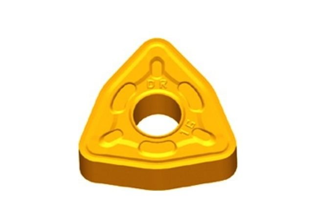
ESTool WNMG Insert
Description:
ESTool WNMG Insert, secure cutting edge, positive rake angle that varies along the edge to negative in order to prevent chipping. Special design reduces cratering. Used for carbon and alloy steel, stainless steel and high temperature alloys, steel and cast iron.
Feature:
- 80° Trigon insert
- Double sided
- Negative rake
- Available in a range of radius for finishing, general purpose and rough turning
- Wear resistant and durable
- Coating: PVD or CVD
- Internal/External turning inserts
| ESTool WNMG Insert |
| DF |
| Insert shape |
?Type |
?Size (mm) |
| L |
ΦI.C |
S |
Φd |
r |
| ?DF Finishing |
WNMG06T304-DF |
6.5 |
9.525 |
3.97 |
3.81 |
0.4 |
| WNMG06T308-DF |
6.5 |
9.525 |
3.97 |
3.81 |
0.8 |
| WNMG06T312-DF |
6.5 |
9.525 |
3.97 |
3.81 |
1.2 |
| WNMG060404-DF |
6.5 |
9.525 |
4.76 |
3.81 |
0.4 |
| WNMG060408-DF |
6.5 |
9.525 |
4.76 |
3.81 |
0.8 |
| WNMG060412-DF |
6.5 |
9.525 |
4.76 |
3.81 |
1.2 |
| WNMG080404-DF |
8.7 |
12.7 |
4.76 |
5.16 |
0.4 |
| WNMG080408-DF |
8.7 |
12.7 |
4.76 |
5.16 |
0.8 |
| WNMG080412-DF |
8.7 |
12.7 |
4.76 |
5.16 |
1.2 |
| WGF |
| Insert shape |
Type |
?Size (mm) |
| L |
ΦI.C |
S |
Φd |
r |
| WGF Finishing wiper |
WNMG060404-WGF |
6.5 |
9.525 |
4.76 |
3.81 |
0.4 |
| WNMG060408-WGF |
6.5 |
9.525 |
4.76 |
3.81 |
0.8 |
| WNMG080404-WGF |
8.7 |
12.7 |
4.76 |
5.16 |
0.4 |
| WNMG080408-WGF |
8.7 |
12.7 |
4.76 |
5.16 |
0.8 |
| SF |
| Insert shape |
?Type |
?Size (mm) |
| L |
ΦI.C |
S |
Φd |
r |
| ?SF Finishing |
WNMG06T304-SF |
6.5 |
9.525 |
3.97 |
3.81 |
0.4 |
| WNMG06T308-SF |
6.5 |
9.525 |
3.97 |
3.81 |
0.8 |
| WNMG06T312-SF |
6.5 |
9.525 |
3.97 |
3.81 |
1.2 |
| WNMG060404-SF |
6.5 |
9.525 |
4.76 |
3.81 |
0.4 |
| WNMG060408-SF |
6.5 |
9.525 |
4.76 |
3.81 |
0.8 |
| WNMG080404-SF |
8.7 |
12.7 |
4.76 |
5.16 |
0.4 |
| WNMG080408-SF |
8.7 |
12.7 |
4.76 |
5.16 |
0.8 |
| WNMG080412-SF |
8.7 |
12.7 |
4.76 |
5.16 |
1.2 |
| EF |
| Insert shape |
?Type |
?Size (mm) |
| L |
ΦI.C |
S |
Φd |
r |
| EF Finishing |
WNMG06T304-EF |
6.5 |
9.525 |
3.97 |
3.81 |
0.4 |
| WNMG06T308-EF |
6.5 |
9.525 |
3.97 |
3.81 |
0.8 |
| WNMG06T312-EF |
6.5 |
9.525 |
3.97 |
3.81 |
1.2 |
| WNMG060404-EF |
6.5 |
9.525 |
4.76 |
3.81 |
0.4 |
| WNMG060408-EF |
6.5 |
9.525 |
4.76 |
3.81 |
0.8 |
| WNMG080404-EF |
8.7 |
12.7 |
4.76 |
5.16 |
0.4 |
| WNMG080408-EF |
8.7 |
12.7 |
4.76 |
5.16 |
0.8 |
| NF |
| Insert shape |
?Type |
?Size (mm) |
| L |
ΦI.C |
S |
Φd |
r |
| NF Finishing |
WNEG080404-NF |
8.7 |
12.7 |
4.76 |
5.16 |
0.4 |
| WNEG080408-NF |
8.7 |
12.7 |
4.76 |
5.16 |
0.8 |
| WGM |
| Insert shape |
?Type |
?Size (mm) |
| L |
ΦI.C |
S |
Φd |
r |
| WGMSemi-finishing Wiper |
WNMG060408-WGM |
6.5 |
9.525 |
4.76 |
3.81 |
0.8 |
| WNMG060412-WGM |
6.5 |
9.525 |
4.76 |
3.81 |
1.2 |
| WNMG080408-WGM |
8.7 |
12.7 |
4.76 |
5.16 |
0.8 |
| WNMG080412-WGM |
8.7 |
12.7 |
4.76 |
5.16 |
1.2 |
| PM |
| Insert shape |
?Type |
?Size (mm) |
| L |
ΦI.C |
S |
Φd |
r |
| ?PM? Semi-finishing |
WNMG060408-PM |
6.5 |
9.525 |
4.76 |
3.81 |
0.8 |
| WNMG060412-PM |
6.5 |
9.525 |
4.76 |
3.81 |
1.2 |
| WNMG080404-PM |
8.7 |
12.7 |
4.76 |
5.16 |
0.4 |
| WNMG080408-PM |
8.7 |
12.7 |
4.76 |
5.16 |
0.8 |
| WNMG080412-PM |
8.7 |
12.7 |
4.76 |
5.16 |
1.2 |
| WNMG080416-PM |
8.7 |
12.7 |
4.76 |
5.16 |
1.6 |
| WNMG080608-PM |
8.7 |
12.7 |
6.35 |
5.16 |
0.8 |
| DM |
| Insert shape |
Type |
Size (mm) |
| L |
ΦI.C |
S |
Φd |
r |
| DM? Semi-finishing |
WNMG06T304-DM |
6.5 |
9.525 |
3.97 |
3.81 |
0.4 |
| WNMG06T308-DM |
6.5 |
9.525 |
3.97 |
3.81 |
0.8 |
| WNMG06T312-DM |
6.5 |
9.525 |
3.97 |
3.81 |
1.2 |
| WNMG060408-DM |
6.5 |
9.525 |
4.76 |
3.81 |
0.8 |
| WNMG060412-DM |
6.5 |
9.525 |
4.76 |
3.81 |
1.2 |
| WNMG080404-DM |
8.7 |
12.7 |
4.76 |
5.16 |
0.4 |
| WNMG080408-DM |
8.7 |
12.7 |
4.76 |
5.16 |
0.8 |
| WNMG080412-DM |
8.7 |
12.7 |
4.76 |
5.16 |
1.2 |
| WNMG080416-DM |
8.7 |
12.7 |
4.76 |
5.16 |
1.6 |
| EM |
| Insert shape |
?Type |
?Size (mm) |
| L |
ΦI.C |
S |
Φd |
r |
| EM Semi-finishing |
WNMG06T304-EM |
6.5 |
9.525 |
3.97 |
3.81 |
0.4 |
| WNMG06T308-EM |
6.5 |
9.525 |
3.97 |
3.81 |
0.8 |
| WNMG06T312-EM |
6.5 |
9.525 |
3.97 |
3.81 |
1.2 |
| WNMG060404-EM |
6.5 |
9.525 |
4.76 |
3.81 |
0.4 |
| WNMG060408-EM |
6.5 |
9.525 |
4.76 |
3.81 |
0.8 |
| WNMG080404-EM |
8.7 |
12.7 |
4.76 |
5.16 |
0.4 |
| WNMG080408-EM |
8.7 |
12.7 |
4.76 |
5.16 |
0.8 |
| WNMG080412-EM |
8.7 |
12.7 |
4.76 |
5.16 |
1.2 |
| NM |
| Insert shape |
?Type |
?Size (mm) |
| L |
ΦI.C |
S |
Φd |
r |
| NM? Semi-finishing |
WNMG080408-NM |
8.7 |
12.7 |
4.76 |
5.16 |
0.8 |
| WNMG080412-NM |
8.7 |
12.7 |
4.76 |
5.16 |
1.2 |
| DR |
| Insert shape |
?Type |
Size (mm) |
| L |
ΦI.C |
S |
Φd |
r |
| DR Roughing |
WNMG060408-DR |
6.5 |
9.525 |
4.76 |
3.81 |
0.8 |
| WNMG060412-DR |
6.5 |
9.525 |
4.76 |
3.81 |
1.2 |
| WNMG080408-DR |
8.7 |
12.7 |
4.76 |
5.16 |
0.8 |
| WNMG080412-DR |
8.7 |
12.7 |
4.76 |
5.16 |
1.2 |
| WNMG080416-DR |
8.7 |
12.7 |
4.76 |
5.16 |
1.6 |
| SNR Roughing |
| Insert shape |
?Type |
?Size (mm) |
| L |
ΦI.C |
S |
Φd |
r |
| SNR Roughing |
WNMG080408-SNR |
8.7 |
12.7 |
4.76 |
5.16 |
0.8 |
| WNMG080412-SNR |
8.7 |
12.7 |
4.76 |
5.16 |
1.2 |
| Insert shape |
?Type |
?Size (mm) |
| L |
ΦI.C |
S |
Φd |
r |
| Slotless |
WNMA06T308 |
6.5 |
9.525 |
3.97 |
3.81 |
0.8 |
| WNMA060404 |
6.5 |
9.525 |
4.76 |
3.81 |
0.4 |
| WNMA060408 |
6.5 |
9.525 |
4.76 |
3.81 |
0.8 |
| WNMA060412 |
6.5 |
9.525 |
4.76 |
3.81 |
1.2 |
| WNMA080404 |
8.7 |
12.7 |
4.76 |
5.16 |
0.4 |
| WNMA080408 |
8.7 |
12.7 |
4.76 |
5.16 |
0.8 |
| WNMA080412 |
8.7 |
12.7 |
4.76 |
5.16 |
1.2 |
| WNMA080416 |
8.7 |
12.7 |
4.76 |
5.16 |
1.6 |
Hot Sales Products:
Milling inserts
|
Cermet Inserts
|
CNMG Insert
|
CCGT Insert
|
VCMT Insert
The Carbide Inserts Website: https://www.estoolcarbide.com/product/wcmt080412-u-drill-inserts-p-1209/
latheinserts
July 8, 2023
ESTool RCGX Insert
Description:
ESTool RCGX Insert, ISO Ceramic Indexable Turning Insert. Semi-finishing carbide inserts for aluminum.
?Feature:
- Model number: RCGX0803MO-LH
- Coating: nc-TiAIN
- Material: Hard Alloy
- Hardness: >60HB
- Coating: CVD, PVD
- Usage: External Turning Tool
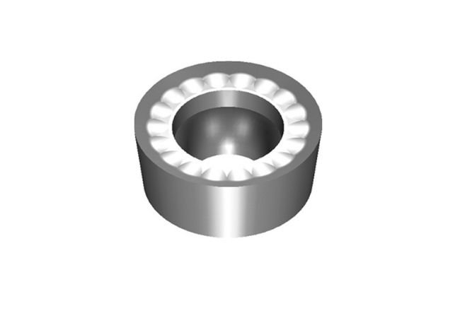
| ESTool RCGX Insert |
| Insert shape |
?Type |
?Size (mm) |
| L |
ΦI.C |
S |
Φd |
| LH? ? ? ? ? ? ? ? ? ? ? ? ? Aluminum processing |
RCGX0803MO-LH |
8.0 |
8.0 |
3.18 |
3.36 |
Hot Sales Products:
Carbide Drilling Inserts
|
Shoulder Milling Inserts
|
Carbide Grooving Inserts
|
tungsten carbide inserts
|
Cutting Inserts
|
CNC Inserts
The Carbide Inserts Website: https://www.estoolcarbide.com/product/tnmg-pressing-cermet-inserts-p-1198/
latheinserts
July 7, 2023
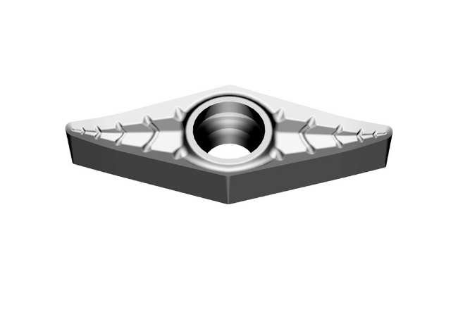
ESTool VCGX Insert
Description:
ESTool VCGX Inserts, VCGX carbide High Polish Turning Insert for Aluminum Applications.
Feature:
- 35° Rhombic insert
- Single sided
- Positive rake
- 7° side clearance
- Screw-On Style Insert
- For Aluminum Applications
| ESTool VCGX Insert |
| LC |
| Insert shape |
?Type |
?Size (mm) |
| L |
ΦI.C |
S |
Φd |
r |
| LC Aluminum processing |
VCGX110301-LC |
11 |
6.35 |
3.18 |
2.8 |
0.1 |
| VCGX110302-LC |
11 |
6.35 |
3.18 |
2.8 |
0.2 |
| VCGX110304-LC |
11 |
6.35 |
3.18 |
2.8 |
0.4 |
| VCGX110308-LC |
11 |
6.35 |
3.18 |
2.8 |
0.8 |
| VCGX160404-LC |
16.6 |
9.525 |
4.76 |
4.4 |
0.4 |
| VCGX160408-LC |
16.6 |
9.525 |
4.76 |
4.4 |
0.8 |
| VCGX160412-LC |
16.6 |
9.525 |
4.76 |
4.4 |
1.2 |
| VCGX220530-LC |
22 |
12.7 |
5.56 |
5.5 |
3.0 |
| LH |
| Insert shape |
?Type |
?Size (mm) |
| L |
ΦI.C |
S |
Φd |
r |
| LH Aluminum processing |
VCGX110202-LH |
11 |
6.35 |
2.38 |
2.8 |
0.2 |
| VCGX110204-LH |
11 |
6.35 |
2.38 |
2.8 |
0.4 |
| VCGX110301-LH |
11 |
6.35 |
3.18 |
2.8 |
0.1 |
| VCGX110302-LH |
11 |
6.35 |
3.18 |
2.8 |
0.2 |
| VCGX110304-LH |
11 |
6.35 |
3.18 |
2.8 |
0.4 |
| VCGX110308-LH |
11 |
6.35 |
3.18 |
2.8 |
0.8 |
| VCGX160402-LH |
16.6 |
9.525 |
4.76 |
4.4 |
0.2 |
| VCGX160404-LH |
16.6 |
9.525 |
4.76 |
4.4 |
0.4 |
| VCGX160408-LH |
16.6 |
9.525 |
4.76 |
4.4 |
0.8 |
| VCGX160412-LH |
16.6 |
9.525 |
4.76 |
4.4 |
1.2 |
| VCGX220530-LH |
22 |
12.7 |
5.56 |
5.5 |
3.0 |
Hot Sales Products:
Cemented Carbide Inserts
|
Milling inserts
|
WNMG Insert
|
APKT Insert
|
TCMT Insert
|
TNGG Insert
The Carbide Inserts Website: https://www.estoolcarbide.com/product/vbmt-pressing-cermet-inserts-p-1199/
latheinserts
July 6, 2023